Most recent threads @ RevitForum.org

Thursday, December 17, 2009

Rudolf the Revitdeer

Let´s just get it out in the open... I have way to much sparetime on my hands :-)

Was just playing around with rendering and lightfixtures - so why not make a Revitdeer ?
I´m of to Qatar in a few days, where I´ll be spending the holidays with my family - So Merry Xmas to everyone, AND a happy New Year !


"Low" walls vs. Cutplanes

When working with low walls (Shorter than 6´-0" or 1828,8 mm) Revit will NOT display it as cut, despite having the cutplane set below that height... To my surprise, this is actually documentet in the help files - so i might as well admit to never have read the help files :-)

"Walls shorter than 6 feet (approximately 1.83 meters) are not cut, even if they intersect the cut plane.

The 6 feet are measured from the top of the bounding box to the bottom of the primary view range. For example, if you create a wall with a sloped top face, when the top of the wall is 6 feet away from the bottom of the primary view range, the wall is cut at the cut plane. When the top of the wall is less than 6 feet, the entire wall shows as projection even where it intersects the cut plane. This behavior always occurs when the Top Constraint property for the wall is specified as Unconnected."

The below image (from the help files), is doing a great job explaining the functions of the view range, and the cutplane bahavior:


Thursday, December 3, 2009

Hotfix - Crash when modifying walls update 2 & subscription advantage pack release

This hotfix addresses issues related to deleting or modifying walls, a crash may occur.


Applies to WU2 (Update 2 Build 20090917_1515 ) and WU3 (Update 3 Subscription Advantage Build 20090925_1815 ) of:
Autodesk® Revit® Architecture 2010
Autodesk® Revit® MEP 2010
Autodesk® Revit® Structure 2010

Download the Hotfix at: Autodesk

Monday, November 9, 2009

Placed components override wall lineweights

Had a question today, regarding components which would override the lineweight of the walls they where placed up against.


The solution:
1. Open the component (family) in the family editor
2. Locate the build in masking region
3. In the element properties of the masing region, uncheck the "Draw in Foreground" box
4. Hit "OK"
5. Create a new Ref. Plane, just above the Ref. Level, and name it "Mask"
6. Select the masking region, and set it´s work plane to the new "Mask" Ref. Plane
7. Load the component into your project.

Saturday, November 7, 2009

Formula to return the highest value

For the family builders, here´s a quick trick to return the highest of three values (user inputs)

We need something like the following parameters:

Length A (User input)
Length B (User input)
Length C (User input)
Calc (Only used to get our final result)
Return Length (Returns the greatest of the three length parameters)

The formulas needed goes like this:

Calc = if(Length A > Length B, Length A, Length B)

Return Length = if(Calc > Length C, Calc, Length C)


Download the sample family from HERE

Edit:

While talking about this topic at the Augi Forums, Joe Zhou came up with this genius formula (The result is the same, but you won´t need the "Calc" parameter...

Return Length = if(and(or(Length A > Length B, Length A = Length B), or(Length A > Length C, Length A = Length C)), Length A, if(and(or(Length B > Length A, Length B = Length A), or(Length B > Length C, Length B = Length C)), Length B, if(and(or(Length C > Length A, Length C = Length A), or(Length C > Length B, Length C = Length B)), Length C, 0 mm)))

OK... the formula itself is a nightmare, but it WORKS !

Tuesday, November 3, 2009

Design Options - Elevation Bug

Yesterday, I was explaining Design Options to a client, and went thru the setting of different views for the options - It turned out to a bit of a nightmare. First I startet with setting up the View Properties for a plan view, then a Section View

But when I went to set up the Elevation Views, something was missing:


So I went looking for it in other elevation views, but still no luck... so I told the Client not to do Design Options which would affect Elevevation Views.... Not really.... i´m sure it´s a BUG, but the under Visibility/Graphics, it´s possible to set the desired Design Option:
Hope "The Factory" is gonna fix this before 2020 :-)

Saturday, October 31, 2009

Revision Date on Drawinglist

Revit won´t let us add the current revision date to the drawing list, and since almost all my clients wants the information on the drawing list, I came up with this simple workaround.

1. Don´t use the Date field in the "Sheet Issues/Revisions" dialog, instead type the date just in front of the description.
2. Make a drawing list that displays the "Current Revision Description" field
3. Change the titleblock revision schedule to display only "Revision Number" and "Revision Description" (delete the "Revision Date" field), and add some line work, to seperate the "Date" from the "Description"

Autodesk really needs to fix this - i´m sure they intended to add this feature in version 2010, when they added the "Current Revision" and "Current Revision Description" to the drawing list fiels anyway.......


Simple, but get´s the job done :-)

Controlling user inputs in families

When building Revit families, and wanting to avoid nightmares, it may be useful to be in control of the user inputs. It could be a door that can´t be made if it´s more than 1200 mm´s (4´-0") wide.

Now, there´s a couple of ways to aproach this, but only one of them will actually tell the user that the input is not acceptable, I tend to combine two methods - 1. Warning & 2. Control

Warning Method

For this we need a custom parameter (yes/no) called "Width Warning", with a formula like this

not(Width < 1200 mm)


Now, create some model text, with a warning to the user - choose element properties for the model text, and aply the "Width Warning" parameter under "Graphics > Visible"


Now, if a user inputs 1200 mm´s or more as the width, the model text will show, and tell the user to correct the problem.

Control Method

It´s also possible to control the input, just in case that the user chooses to ignore the warning.

Create a new length parameter called "Controlled Width" and ad a formula like this:

if(Width > 1200 mm, 1200 mm, Width)


Now change the label for the current width dimension, to the new "Controlled Width" parameter.

Now the user get´s  a warning, and the door keeps a max. width of 1200 mm´s, even if the user input is greater than 1200 mm´s.


Download the example Door family

Wednesday, October 21, 2009

Quick printing of all sheets in a project.

As a freelance Revit Consultant, I run into many undocumentet nightmares with Revit - One of them is described below:

The print dialog in Revit, is missing some MAJOR features, like beeing able to print by "Sheet Size" - Here in Denmark, architects usually puts the various drawings on many different sheet sizes,which makes printing entire projects a truly nightmare.

On request of a client of mine, I finally contacted the "Factory", and togheter we came up with the following solution:

1. Forget about the fu***** print dialog in Revit - It´s useless.
2. So instead, go to one of the sheets in your project.
3. Choose Export > DWF:
4. Choose "Sheets in the Model" > "Select all"
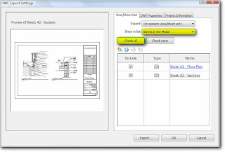
5. Choose "DWF Properties" > "Print Setup"
6. Choose "Use Sheet Size" for the paper size
7. Click "OK" > "Export" and save your DWF file to the hard drive

8. And now, to the "UNDOCUMENTET" part > Double-click on the printer's icon in the Control Panel or select Settings in the Start menu and then choose the Printers option. > In the Printers window, select Server Properties from the File menu.

Now create new forms for your custom paper sizes - this will affect all installed printers.

If  you´re going to print to PDF, there´s another "WEIRD AND UNDOCUMENTET" part.

REPEAT the custom form creation part, but di it IN REVERSE - so that you enter the width as the height, and the height as the width. - Don´t ask me WHY !! But it´s the only way to get a PDF printer to pick up the custom sizes automaticly (Have tested with Adobe PDF, and Cute PDF)

My thanks go to Luciane Conceicao from the "Factory", who came up with the reversing part !


8. Open the saved DWF file in Autodesk Design Review, and then Print the entire sheets to your Plotter and/or PDF Writer - Remember to check "Choose paper source by DWF print" > Set scale to "100%" and "Center on paper"
This may seem like a lot of steps, but once the custom paper sizes / forms are created, it really takes no time to print entire projects, even with different sheet sizes.

BTW - Sorry about the missing screen captures from the print server properties (My OS is in Danish, so it would not make any sence to most people anyway)

It´s my goal to be posting more of these undocumentet NIGHTMARES, but this is it for now.